Introduction
The reference book aims to be the more complete and up to date source of information regarding the various products and systems in our organisation.
Universal Flight System
Albatross encompasses the entire airborne acquisition systems and all their components. This includes the hardware components such as cameras, triggering controller, tripod and screen, as well as all the software components including the acquisition controller, the user interface, backup utilities and spase upload.
The universal flight system, or UFS, specifically refers to the software components necessary for manned aircraft data capture. They will each be described in detail in the following pages.
Overview

UFS consists seven custom software components. Dataflow starts at the acquisition controller which is responsible for sensor and controller interfacing. It configures and acquires the images and telemetry from the cameras and SMC.
The metadata generated by the acquisition controller is then passed to the telemetry processor which digests it to produce some higher level information for the pilot and operator interfaces.
Information about the file locations is also passed to the Backup Utility which is responsible for discovering available external storage drives and copying all image and metadata files to redundant external drives whenever possible.
Reviewer Server is a tool which lets the user interface query information about passes, their review status, and serves images to the front end for the operator to review. It is also responsible for storing the review status of said images.
Middleware is basically a crud application on top of the PosgreSQL database that stores all the site and recording information. It also serves some higher level and higher latency functions such as generating flight lines and coverage maps.
Primary App is responsible for orchestration and monitoring of the aforementioned systems. It is launched by systemd on system startup and is responsible for spawning the sub-processes that make up UFS. It allows control and monitoring of those subprocesses via a simple REST interface.
Lastly, the UFS Interface is a web app that serves as the main user interface for the system. It provides all the visibility and control surfaces needed to capture data efficiently using UFS. It is served by a nginx engine running on the onboard computer and connects to all the earlier mentioned systems.
Runtime environment
The various processes outlined above will interact together in several ways, some of those mechanism, such as ZMQ sockets
do require that both processes agree on what port to use. Some other elements, like the file storage location for the
acquisition controller, are also deserving of some flexibility. As such, those elements are not hard coded and instead
expect environment variables to be set. To make environment setup simpler for everyone, the use of a .env file is highly
recommended.
Every process will start by trying to load the ${HOME}/.env file and the variables within. Each process will then use
whatever environment variable they need out of said file. If one chooses not to use said .env file, they will be responsible
for ensuring the environment contains the necessary variables. Failure to do so will cause the various processes to crash
on launch.
Acquisition Controller
Table of Contents
- Overview
- Hardware Interfaces
- Control Interfaces
- Overview
- Endpoints
- GET
/control - GET
/control/start - GET
/control/stop - GET
/control/telemetry - GET
/control/list_cameras/{camera_name} - GET/POST
/control/{camera_designation}/set - GET
/control/{camera_designation}/execute/{command_name - GET
/control/{camera_designation}/query/{parameter_name} - GET
/control/{camera_designation}/list_parameters - GET
/control/{camera_designation}/image - GET/POST
/control/environment - GET
/control/gps - GET
/control/disk_space - GET
/control/set_rate - GET
/control/status
- GET
- Data Publishing Interfaces
Overview
The acquisition controller is responsible for acquiring images from the cameras, configuring said cameras, synchronizing the receptions with some telemetry measurements, and writing all of that to disk. Most of the time, that is going to be a temporary location but managing that falls outside the responsibility of the acquisition controller. We are only concerned with getting images, saving them to disk, and lining up the images with a telemetry sample at this stage.
Hardware Interfaces
To acquire images, the acquisition controller needs cameras and a trigger controller. The cameras can be connected via USB, ethernet, and really any number of physical interfaces, as long as a driver is coded for it. The trigger controller is known everywhere as the SMC. This SMC is connected via serial USB.
Control Interfaces
Overview
Control over the acquisition controller is possible via a REST style API. An HTTP request handler is built into the acquisition controller and serves a few paths to allow limited control over the devices and visibility into the state of the system. In the first implementation, the HTTP handler listens on port 34568 for incoming requests.
This interface allows the user to start and stop the capture of images, but also to set some camera properties and activate some features of specific cameras.
Endpoints
GET /control
This endpoint serves a very simple HTML page that allows you to drive the other endpoints of this service. This is only intended as a testing facility.
GET /control/start
This endpoint will start recording images. Query arguments are used to determine where the image files shall be saved and how to name them.
Query parameters:
-
location
- Type: string
- Description: Absolute path where the images are to be saved
- Optional: yes
-
prefix
- Type: string
- Description: text that shall be prepended to the image names when saving.
- Optional: yes
Notes: If the location and prefix are empty, the images will be saved next to the executable location. If the prefix is
present, the images will be named as follows: prefix_<cam_name>_<count>.<extension> where cam_name and extension is
extracted from the XML configuration file, and count is an auto-incrementing number that will ensure each name is
unique.
GET /control/stop
This endpoint will suspend the recording of images.
GET /control/telemetry
The route will return a JSON blob containing the latest telemetry report received from the SMC.
GET /control/list_cameras/{camera_name}
The route will return a JSON blob containing the list of cameras loaded by the acquisition controller and their parameters with values.
Path parameters:
- camera_name
- Type: string
- Description: name of the camera, as defined in the XML configuration file.
- Optional: yes
Query parameters:
- includeSmc
- Type: bool
- Description: dictates if the SMC should be listed with the other sensors present.
- Optional: yes
Return value:
[
    {
        "model": "",
        "name": "",
        "serial": "",
        "spectrum": "",
        "status": {
            "message": "",
            "state": "normal", "degraded" or "error"
        }
    },
    {

    }
]
GET /control/{camera_designation}/list_parameters
Each camera has different capabilities and different parameters that can be set and queried. They are defined in the XML configuration file. This method will list out those parameters
Path parameters:
- camera_designation
- Type: string or int
- Description: name of the camera, as defined in the XML configuration file. Or index of the camera in the array held in the acquisition controller. There is no guarantee regarding the ordering in said array.
- Optional: no
Additional Information
There are a few parameters accessible to control the performance of the camera drivers.
Scale- Description: ratio by which to scale the native image. A value less than 1 will reduce the size of the image and speedup the compression and transfer when getting the image.
- Type: float
Quality- Description: Value between 0 (worst quality) and 100 (almost lossless) indicating the amount of compression to apply on the image when converting to webp.
- Type: integer
GET,POST /control/{camera_designation}/set
A few parameters can be changed at runtime. Those parameters can vary for each camera. This endpoint allows the caller to assign a new value to different runtime parameters.
Path parameters:
- camera_designation
- Type: string or int
- Description: name of the camera, as defined in the XML configuration file. Or index of the camera in the array held in the acquisition controller. There is no guarantee regarding the ordering in said array.
- Optional: no
Query parameters:
<parameter_name>- Type: bool, float, int
- Description: This is the name of the parameter for which we want to set a value. This name should appear in the XML configuration file and the value assigned must be of the same type as what is declared in the XML. There can be any number of parameters declared in the query.
- Optional: yes
Request body: The list of parameters to set can also extend to the body, as a JSON object following the format:
{
  "<param_name1>": value,
  "<param_name2>": value,
  ...

  "<param_nameN>": value
}
The parameters set in the query and in the body will be merged to a single list all applied to the camera.
GET /control/{camera_designation}/execute/{command_name}
Some cameras, namely the IR cameras, have commands that can be executed. Good example of this is the non-uniformity correction of the FLIR. This endpoint allows the execution of some commands on some cameras. The commands can be found in the list of parameters returned by the list command
Path parameters:
-
camera_designation
- Type: string or int
- Description: name of the camera, as defined in the XML configuration file. Or index of the camera in the array held in the acquisition controller. There is no guarantee regarding the ordering in said array.
- Optional: no
-
command_name
- Type: string
- Description: name of the command to execute, as defined in the XML file.
- Optional: no
GET /control/{camera_designation}/query/{parameter_name}
Retrieve the current value of a parameter.
Path parameters:
-
camera_designation
- Type: string or int
- Description: name of the camera, as defined in the XML configuration file. Or index of the camera in the array held in the acquisition controller. There is no guarantee regarding the ordering in said array.
- Optional: no
-
parameter_name
- Type: string
- Description: name of the parameter to query, as defined in the XML file.
- Optional: no
GET /control/{camera_designation}/image
Retrieve the latest image acquired by the designated camera. Image returned will be in the webp format. Scale and
compression ratio of the image are controllable using the .../set route.
Path parameters:
- camera_designation
- Type: string or int
- Description: name of the camera, as defined in the XML configuration file. Or index of the camera in the array held in the acquisition controller. There is no guarantee regarding the ordering in said array.
- Optional: no
GET/POST /control/environment
Post to update, get to read, environmental readings. At this time, the only source for those values is the UI so the get will be empty until a post is made. Until a more automated source of data can be integrated, the full control and responsibility of this data lies with the UI.
Query parameters:
*- Type: double
- Description: any query parameter is added to the map of values that will be dumped to the metadata package when an image is captured.
- Optional: no
GET /control/gps
Endpoint to write new GPS antenna offsets in the INS. This route will forward the x, y, z offsets to the SMC and
eventually to the INS where they will be written to flash and persist after power cycles. The endpoint will also cause
the INS to be reset, which is necessary for the offsets to be applied to the filter. Offsets are to be measured in
meters. The coordinate frame follows the right hand rule with x pointing out of the lens, y pointing towards the
back of the plane when the rig is looking out the right side window, and z pointing towards the ground.
Query parameters:
x- Type: double
- Description: offset in the
xaxis
y- Type: double
- Description: offset in the
yaxis
z- Type: double
- Description: offset in the
zaxis
GET /control/disk_space
Endpoint to query the remaining disk space available in the currently selected save location.
Return value:
{
  "path": "path",
  "capacity": capacity in bytes
  "free":  free in bytes
  "available": available in bytes
  "available_gb":  available in gigabytes
}
GET /control/set_rate
Set the SMC trigger rate for some device. The device names are strings configured in the firmware of the SMC.
Query parameters:
ident:- Type: string
- Description: name of the device who's rate is to be set
rate:- Type: double
- Description: rate of trigger in hertz
GET /control/status
Endpoint to get the status of the capture recording.
Return value:
{
  "capture_running": boolean
}
Data Publishing Interfaces
Telemetry information, along with the corresponding image file association information, is also recorded as files, specifically JSON files. Those files are stored in the same directory next to the image files.
Telemetry
For use of this telemetry data outside the acquisition controller, the same content is also published on a ZMQ socket.
Port 5556 is used for this publisher and the content published on this socket is defined by the protobuf structure
located in this repository Specifically,
the AcquisitionControllerMessage is generated and serialized before being published. This message contains all the
telemetry information received by the controller. It is published for every telemetry sample received, so at a much
higher rate than the incoming images, a field in the message indicates if this frame aligns with some images.
Files
A second ZMQ publisher running on port 5550 publishes the file synchronization information. The content of this
publisher follows the ImageMatch structure defined
in this repository. It essentially
associates a series of files with a telemetry identifier. This message is published once when a new synchronization
match is established.
Architecture of the Acquisition Controller
Class diagram
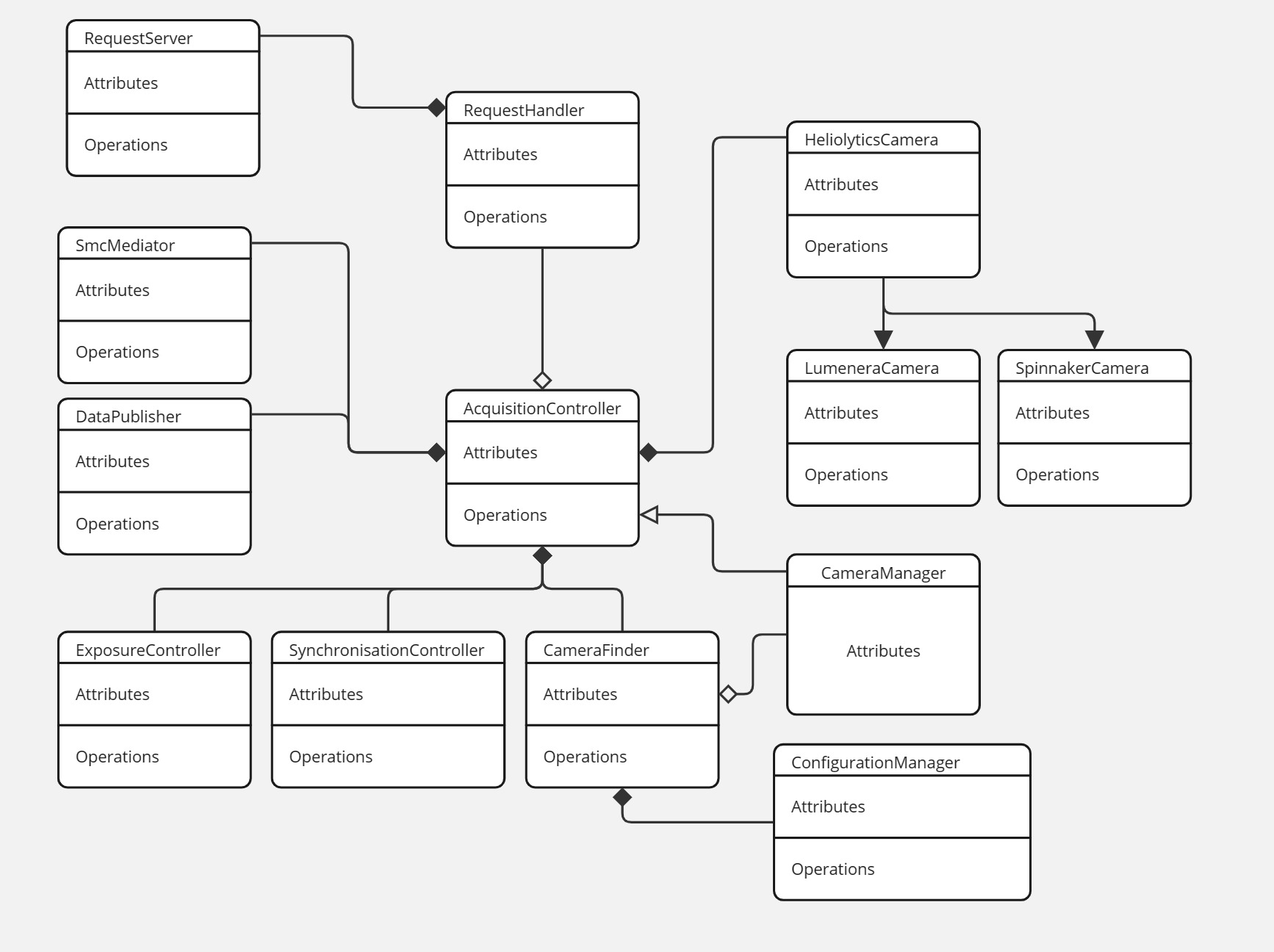
Modules
Cameras
To support a variety of camera protocols, a generic HeliolyticsCamera serves as the base class for all types of camera
possibly supported by the controller. Currently, the cameras on the rig utilize two protocols, the proprietary Lumenera
protocol and the standard GenICam protocol. SDKs are distributed for both protocols so a wrapper is created to implement
the base interface, LumeneraCamera and SpinnakerCamera respectively. Additionally, a CameraFinder class is
responsible for enumerating and constructing the cameras according to the configuration listed in the config files.
Again, each protocol may have a different enumeration process so protocol specific code must be implemented in the
CameraFinder. Once constructed, the camera pointer is handed over to the CameraManager who will own the
resource for the rest of its lifetime.
Exposure Control
As was the case in the legacy AUI implementation, UFs has the ability to dictate exposure parameters, namely shutter speed and gain,of a camera based on the auto-exposure settings provided by another camera. The most likely use case for this feature is the use of the HFR camera to dictate the exposure parameters of the highres LUM camera.
To achieve this function, cameras can be registered as exposure "master" or exposure "slaves". A callback will be registered with the master which is to be called when the master receives a new image. This callback is responsible for recomputing new exposure parameters and reconfigure the slave cameras.
SMC
Communication with the SMC is handled by a helper class conveniently named SmcMediator. It provides the functions to
connect, receive, and decode the messages from the SMC. Status updates are sent asynchronously from the SMC and thus
all the reception and decoding logic of the mediator is executed in a thread detached from the main thread. To be
notified of new statuses, the AcquisitionController registers a callback function with the mediator. That function is
invoked from the SMC reception thread so logic in the callback should be kept to a minimum.
In the current implementation, the status is added to a queue along with a timestamp. The processing of that queue happens in the main thread.
Synchronization
Without a doubt, the single hardest challenge in the acquisition controller is to synchronise the images received. In order to be usable, the images from each camera must be matched to a telemetry update. Only then do we have a meaningful frame. Unfortunately there is no easy and robust solution to this yet. The current strategy utilizes a simple first in first out queue mechanism.
The synchronization logic lives in a separate class, the SynchronizationManager which registers a callback with each
camera node. When an image is stored, the callback is called and an entry is added to the corresponding camera's queue.
Same thing when a telemetry sample is received.
Synchronisation is achieved by assuming the first element of each queue belongs together to form a frame. This is a very vulnerable assumption which relies on the camera nodes to never miss an image, or notify the manager that an image was missed should some error happen.
SMC
Historically called SMC, the meaning of the acronym has been lost to the ether, but one can speculate as to its origin. Considering it's function is to control and insure the synchronization of the image capture, I would probably argue for something along the lines of Synchronization Management Controller.
As stated, the purpose of the SMC is to synchronize the triggering of the cameras, a task which is the cornerstone of frame-by-frame analysis. The SMC is a homegrown system that includes power distribution electronics and a microcontroller for sensor interface and camera triggering.
Power distribution
The SMC is responsible for providing power to the various systems from a single power source. This is usually either a battery or what is known as plane power, usually in the form of a cigarette lighter plug in the aircraft. For bench testing, the travel kits usually also include an AC-to-DC adapter.
Those power sources can vary in voltage from 10 to 48 volts usually, so the power conversion circuits of the SMC can accommodate input voltages up to 60V. The SMC is then responsible for converting that to the various voltages needed by components on the rig, namely, 24V, 19.5V, 12V and 5V.
This is achieved by a buck-boost converter, the design of which is based on the reference design of the VICOR chip doing the actual level change. This design is implemented in a pair on a separate PCB that is then assembled as a daughter board on the SMC.
Sensor interface
The albatross rig used to be equipped with a laser range finder, the Vectronix LFR3013. This LRF is a UART device. The other sensor on the rig is an inertial navigation unit, a Vectornav VN-200, also a UART device.
To interface with these two devices, the SMC the commonly used dev board Teensy version 4.1 which is based on the iMX RT1060 microcontroller. This is an ARM M7 chip with plenty of flash, and peripherals for all our needs.
Backplane
When talking about the SMC, we usually refer to the complete assembly of a backplane, 3 double vicor daughter boards, and the teensy daughter board. The backplane is a much larger PCB which mainly does signal routing, but some power protection circuitry, namely reverse polarity protection, is also implemented on that board. The reverse polarity protection circuit will short the inputs of the backplane if the input terminals are misconnected, make sure there is a fuse in the loop or things could burn down.
In addition to reverse polarity protection, the backplane also routes several voltage monitoring points to the analog inputs of the microcontroller. Those points are fed through voltage divisors to bring the scale down to the 3.3V windows the ADC operates in, and those divisors, especially on the input, are the main point of limitation for the input voltage range supported by the SMC.
Lastly, the backplane implements an UART to USB cirtuit which allows the SMC to communicate with the computer as a serial device. This implementation was deemed more reliable and controllable than using the USB controller of the microcontroller mainly because of the implementation of the USB peripheral in the RTOS stack chosen.
Software architecture
The software architecture of the SMC is drawn out quite a bit in this diagram but here are the highlights. This software is implemented on top of the Zephyr real-time operating system. Zephyr is essentially used as an abstraction layer simplifying the configuration and management of the hardware peripherals.


Generally speaking, the duties of the microcontroller can be split into 5 categories, LRF measurements, INS measurements, power measurements, camera triggering, and communication with the computer. And those are the 5 main classes of the class diagram above.
Starting with the simple components, the Trigger Controller is a simple management class which utilises the hardware timers to achieve precise frequency timing. Two timers are used, one to trigger the rising edge of the pulses and one to trigger the falling edge. The output signals are set in the timer's interrupt service routine. As such, the logic in that routine is kept to a minimal. The class has other methods to register and configure different trigger lines. The configuration allows support of different frequencies, active high or low, falling or rising pulses, long or short pulses, etc. The class also decodes the UART request to set the rate of some trigger.
The Power Monitor is another pretty simple class, this one focussing on the ADC. The class configures and polls the ADC to measure the various voltage points on the backplane. The mainloop periodically takes a measurement and stores it in cache until the PC communication thread queries for a reading. The Power Monitor class is also responsible for the scaling of each channel, and it's corresponding voltage divisor parameters.
The LRF class is responsible for getting measurements with the LRF. The class uses a UART peripheral to communicate with the sensor, a separate thread is spawned in the class' constructor and polls the sensor every half second for a new distance measurement. The measurement is cached for the PC communication thread when needed.
The INS class is a bit more complex than the previous ones. It is also based on serial communication through a UART to the INS, similar to the LRF, but the communication protocol of the INS is a lot more complex. A reading of the INS is triggered using the Trigger Controller so that the images are in sync with a position frame. Upon triggering, the INS will send out a data packet to the SMC. The format and content of that packet can be configured by the user. Additionally, the INS class can send command packets to the SMC either to reconfigure some settings, read out some values, or query additional information.
Lastly, the SMC class is the main interface into the firmware from the computer. The SMC class is responsible for the serial communication to and from the PC. It decodes messages from the computer and dispatches the payload received to various command handlers that are registered with the class. An example of such handler would be the set rate command previously discussed in the Trigger Controller. The SMC class is also responsible for periodically reporting to the computer with the latest telemetry, power readings, and trigger information.
Middleware
Table of Contents
- REST API
- GET
/mw - POST
/mw/upload - GET
/mw/missions - GET
/mw/missions/{mission_uuid} - DELETE
/mw/missions/{mission_uuid} - GET
/mw/missions/{mission_uuid}/download - POST
/mw/load/{mission_uuid} - GET
/mw/attempt_requests/{mission_uuid} - GET
/mw/coverage/{attempt_uuid} - GET
/mw/missing_coverage/{attempt_uuid} - GET
/mw/flight_lines/{attempt_uuid} - GET
/mw/loaded_mission - PUT
/cache - GET
/cache
- GET
The middleware is the software component on the rig that is responsible for managing missions, coverage, etc. Essentially, the middleware is what makes UFS specific to aerial inspections.
During the planning stage, a mission file is created. This file contains all the information required to take the plane out and capture data. It contains the list of sites that need to be scanned and their geometry, list of contacts and other notes that might be relevant. This mission file is the first input to the middleware.
The middleware also allows the generation of flight lines, lines which will guide the pilot when flying, insuring the field of view of the camera correctly captures the site we are interested in.
REST API
GET /mw
This endpoint serves a very elementary HTML page that allows the most basic file upload. This is meant strictly as a testing facility.
POST /mw/upload & /mw/upload_json
This endpoint allows the user to upload a new mission to the middleware
Query parameters:
- allow_delete
- Type: boolean
- Description: Without this flag, the upload and parsing process will never remove information from the database, setting the flag to true will allow the parser to remove sites from the database if they are removed from the mission file.
- Optional: yes
Body: A file, either a legacy mission XML to the /mw/upload endpoint, or a flight group JSON file to the
/mw/upload_json endpoint.
Return body: Mission created object
{
  "name": "",
  "uuid": ""
}
Notes:
- This can be a new or an existing mission. Upon upload the file is validated against the schema then parsed. The attempts and associated metadata are stored in a database for future examination and retrieval. If a mission is already known, the database will be updated with the information contained in the file.
- Uploading a file that does not list all the attempts known in the database without the allow_delete flag will return status code 409 Conflict to indicate the mismatch of deleted data and missing flag. In that case, the data in the file will be added/updated in the database but nothing will be deleted.
GET /mw/missions
This endpoint fetches the list of mission uploaded to the middleware in the past.
Return body: List of missions known.
[
  {
    "name": "",
    "uuid": ""
  }
]
GET /mw/missions/{mission_uuid}
This endpoint fetches the details of a specific mission.
Path parameters:
- {mission_uuid}
- Type: string
- Description: UUID string of the mission.
- Optional: no
Return body: Json object with the details of the mission
{
  "name": "",
  "uuid": "",
  "last_modified": "timestamp"
}
DELETE /mw/missions/{mission_uuid}
This endpoint deletes a mission from the database.
Path parameters:
- {mission_uuid}
- Type: string
- Description: UUID string of the mission to delete.
- Optional: no
Return body: None
Notes: All data associated with this mission will be removed from the database. This includes attempts, captures, telemetry, coverage, images, everything!
GET /mw/missions/{mission_uuid}/download
This endpoint downloads the latest description of a specific mission.
Path parameters:
- {mission_uuid}
- Type: string
- Description: UUID string of the mission.
- Optional: no
Return body: The XML file that was last uploaded for this particular mission.
POST /mw/load{mission_uuid}
This endpoint loads a mission without having to upload a file. The mission uuid given in the request should exist in the database prior to the call. Error code 404 will be returned otherwise.
Path parameters:
- {mission_uuid}
- Type: string
- Description: UUID string of the mission uuid to load.
- Optional: no
Return body: None
GET /mw/attempt_requests/{mission_uuid}
This endpoint will return the list of attempts associated with the mission selected. Additionally, requesting the details of a mission with this endpoint will cause this mission to be selected as the active mission. This will cause the zmq publisher to relay this mission selection to the telemetry processor.
Path parameters:
- {mission_uuid}
- Type: string
- Description: UUID string of the mission uuid for which to fetch the attempt requests. If no UUID is provided, all requests are returned, regardless of the mission they are associated with.
- Optional: yes
Return body: Array of objects representing the various attempts
[
  {
    "contacts": [
      {
        "email": "",
        "name": "",
        "phone": ""
      }
    ],
    "elevation": "",
    "estimatedTime": "",
    "geometry": {
      geo_json_object
    },
    "name": "",
    "notes": [
      ""
    ],
    "requiredScanAltitude": "",
    "uuid": ""
  }
]
GET /mw/coverage/{attempt_uuid}
Get the area of a site that has been covered by the capture software so far during the attempt.
Path parameters:
- {attempt_uuid}
- Type: string
- Description: the UUID of the attempt for which to fetch the coverage.
- Optional: no
Query parameters:
- review_status
- Type: enum (string)
- Values:
unreviewed,approved,rejected - Description: compute the coverage by selecting only images that have been marked as a specific review status.
- Optional: yes
- spectrum
- Type: string
- Values:
ir,rbg - Description: get coverage of images in the specific spectrum.
- Default: 'ir'
- Optional: yes
Return body: GeoJson object representing the geometry covered.
Notes: Coverage is estimated based on the telemetry received and the site geometry provided in the mission file, specifically the site elevation. The field of view of the cameras is projected onto that surface, and summed over time to build a unified geometry that represents the entire region covered under that attempt.
GET /mw/missing_coverage/{attempt_uuid}
Similar to get coverage but returns the region of a site that has not been covered by that attempt.
Path parameters:
- {attempt_uuid}
- Type: string
- Description: the UUID of the attempt for which to fetch the coverage.
- Optional: no
Query parameters:
- review_status
- Type: enum (string)
- Values:
unreviewed,approved,rejected - Description: compute the coverage by selecting only images that have been marked as a specific review status.
- Optional: yes
- spectrum
- Type: string
- Values:
ir,rbg - Description: get coverage of images in the specific spectrum.
- Default: 'ir'
- Optional: yes
Return body: GeoJson object representing the geometry not covered during the attempt.
Notes: This value is basically site_geometry - coverage
GET /mw/flight_lines/{attempt_uuid}
Generate the flight lines to cover the region that is not covered by an attempt thus far.
Query parameters:
-
heading
- Type: Double
- Description: Which heading should the lines be oriented towards
- Optional: yes
- Default value: 180
-
altitude
- Type: Double
- Description: Altitude above the site at which you want to fly in feet
- Optional: yes
- Default value: 2000
-
pitch
- Type: Double
- Description: Angle off the vertical at which the camera is pointing
- Optional: yes
- Default value: 32
-
buildup
- Type: Double
- Description: Length of the approach line to generate before covering the site
- Optional: yes
- Default value: 1.0
-
overlap
- Type: Double
- Description: Percentage of the field of view that should overlap between two flight lines
- Optional: yes
- Default value: 0.40
-
side
- Type: string
- Description: Which side of the place is the camera mounted on. Can be
leftorright - Optional: yes
- Default value:
right
-
lens_angle
- Type: Double
- Description:
- Optional: yes
- Default value: 10.7
-
review_status
- Type: enum (string)
- Values:
unreviewed,approved,rejected - Description: compute the missing coverage by selecting only images that have been marked as a specific review status.
- Optional: yes
Path parameters:
- {attempt_uuid}
- Type: string
- Description: the UUID of the attempt for which to generate the flight lines. If UUID is missing, this will return the last set of lines generated.
- Optional: yes
Return body: GeoJson object representing the lines to fly.
Notes:
- The algorithm starts by computing the missing coverage for an attempt. Then based on the flight parameters provided, it generates a list of lines that will place the field of view of the camera over the site assuming a straight and level flight.
- Repeated calls may yield different results as the site gets scanned and coverage changes.
GET /mw/loaded_mission
Get the UUID of the mission currently loaded. A mission is loaded when calling the GET /attempt_requests/{mission_uuid}.
PUT /cache
This is a raw buffer where the web application can store a JSON object to be passed between instances of the user interface. The main use case for this is passing data from the operator UI to the pilot UI. Data stored in the cache can be retrieved using the GET method.
Body: A JSON object to be stored.
GET /cache
This is the retrival method for data stored using the PUT method.
Return body: The content of the cache with content_type: application/json headers.
Telemetry Processor
Once part of the middleware, the telemetry processor consumes the telemetry stream published by the acquisition controller and derives some key information from it. Mainly, this means predicting the flight path of the aircraft, projecting the field of view of the cameras, and determining height above ground. This processed information is then published to websockets for the web UI to display.
Web Socket
The rest api is great for fetching data at a slow rate but the polling model is very impractical when the backend wants to push new data to the front end. For this purpose, websockets will be used where the front end shall listen to events pushed by the backend.
Telemetry socket
Running on port 8080, a websocket server accepts connections and will immediately stream telemetry as well as some
values computed from the telemetry. When the socket connection is established, the server will start to stream the
following json object.
{
  "telemetry": {
    "lat": <double>,
    "lon": <double>,
    "alt": <double>,
    "yaw": <double>,
    "pitch": <double>,
    "roll": <double>,
    "undertainty": {
      "lat": <double>,
      "lon": <double>,
      "alt": <double>,
      "yaw": <double>,
      "pitch": <double>,
      "roll": <double>
    }
  },
  "range": <double>,
  "flight_path_projection": <geojson>,
  "fov": [
    {
      "name": <string>,
      "spectrum": <string>,
      "fov": <geojson>
    }
  ],
  "ground_speed": <double>,
  "altitude_above_site": <double>,
  "heading": <double>
}
Roll, pitch, yaw, lat, and lon are the raw values received from the INS; range is the value received from the laser range finder.
flight_path_projection is a set of points showing the predicted future position of the airplane based on the current
linear and angular speeds.
fov is a polygon representing the estimated field of view of the cameras. The projection is based on the estimated
attitude of the rig and the given elevation of the site.
heading is determined based on the north and east components of INS velocity in the NED frame.
altitude_above_site is essentially gps_altitude - site_elevation where site_elevation is derived by finding the
closest site to the current position as explained here.
Architecture of the Telemetry Processor

Modules
Live Telemetry Receiver
The live telemetry receiver is responsible for handling messages coming in from the telemetry socket. Messages from this ZMQ subscriber are deserialized into the proper structure and passed to the LTR which is then responsible for a few things. First, camera field of views are projected to estimate a covered region. Second, the current gps velocity and acceleration is used to make a prediction as to the future flight path of the aircraft. Other pieced of telemetry are interpreted to produce some higher level data, such as plane heading, altitude above site, etc.
All of this information is packaged into a JSON object which is serialized to a string to be pushed through a websocket for the user interface.
Additionally, if the metadata indicates that images were triggered for that sample, the LTR will extract the frame's UUID, enter the frame in the database and send the telemetry sample's UUID over a crossbeam channel to the ImageMatchProcessor.
Live Image Receiver
Similar to the LTR, the Live Image Receiver is responsible for handling the ImageMatch messages published by the Acquisition Controller. Those messages relate a set of image details (camera, serial number, file path, UUID) to a telemetry UUID. The LIR is responsible for extracting the telemetry UUID and sending the image details with the telemetry UUID to the ImageMatchProcessor over a crossbeam channel.
Image Match Processor
Running is a separate thread from the ZMQ subscriptions, the Image Match Processor is responsible for entering the image details in the database. To achieve that, the IMP will inspect the receiver of the LIR and LTR channels for common telemetry UUIDs. When a match is found, the IMP will compute a field of view projection for each image in the details, write that field of view to disk next to the image, and insert an entry in the database tracking that image, the file on disk and the field of view.
Site Manager
The Site Manager is responsible for identifying the closest site to the current position. Only sites in the currently active mission, as received from the middleware, are considered in this matching algorithm. It does so by evaluating the distance between the current position and each site in the currently active mission, and selecting the shortest distance. The elevation of this site is then fetched from the mission data and stored in cache for the field of view projection operations.
Primary App
Table of Contents
The primary app is a daemon that gets launched at startup. This app allows
control and monitoring of the other UFS processes. The app is registered as a
service with systemd and is launched as the heliolytics user; this helps keep
file permissions consistent.
Once launched, the daemon exposes a rest api to control and monitor the status
of all the UFS subprocesses. The daemon is also responsible for collecting and
recording logs from the subprocesses. It is assumed that the subprocesses'
stdout stream will be serialised JSON objects containing the level, timestamp,
module and message fields. If such a message is decoded, it shall be
recorded to a database, file, and syslog.
REST API
A REST server listening on port 8888 serves the following endpoints:
GET /status
This endpoint serves an object with the status of each process.
GET /start/{name}
This endpoint allows starting a process given a certain name in the path.
Query parameters:
- name
- Type: string
- Description: Name of the process to start. The name must be one of the keys in the object returned by the
/statusroute. - Optional: no
GET /stop/{name}
This endpoint allows stopping a process given a certain name in the path.
Query parameters:
- name
- Type: string
- Description: Name of the process to stop. The name must be one of the keys in the object returned by the
/statusroute. - Optional: no
GET /version
This endpoint will interrogate apt to get the installed version number of each package.
Return body: JSON object listing all the UFS packages and their currently installed versions.
Backup Utility
Overview
The purpose of the backup utility is to ensure that all files created by the acquisition controller are safely transferred to redundant external drives. This includes all image and metadata files. To do so, the utility has to discover which drive are connected, mount the partitions if necessary, then examine the partition to find an identifier file. This file, a simple yaml file, shall contain the drive's name, serial number and type, i.e. ifbu, transport, archive, etc.
Mounting Partitions
Before copying the files, the utility must first find where to copy them, this is done by inspecting the kernel status files. Specifically, /proc/partitions gives a list of all the devices connected to the system and the partitions on them. The utility parses that file and finds all entries that correspond to external storage devices. We consider all devices that begin with "sd.+"1 to be external storage devices. Each device should have at least two entries, one for the device pointer itself ("sd."1) and one entry for each partition on the device ("sda\d"1).
This scheme was developed with ubuntu server in mind but the first release of Albatross will utilize ubuntu desktop, which, when logged in, already runs a service to mount new partitions as they are connected. This utility will therefore be disabled until further notice.
Discovering acceptable partitions
Once a list of partitions is created, the utility must determine which partitions are mounted and which are not. This is done by parsing the kernel status file /proc/mounts. By parsing that file, one can find the partitions that are currently mounted and their mount point. The utility then determines if there are entries in the partition list that are not in the mount list and mounts these partitions.
The whole discovery and mounting procedure runs asynchronously from the main thread. When launching the utility, a separate thread is spawned that monitors the partition and mount files and refreshes the list of found devices, mounts and unmounts partitions when devices are connected and disconnected. The DriveManager class is responsible for those functions.
Selecting Backup Locations
With the list of partitions and mount points created earlier, the utility must determine which of those locations are suitable for backup. All the heliolytics drives shall be initialised with a metadata file. This file shall contain the drive's serial number and any other identification we deem necessary, such as a Pokemon name. In addition to this name and serial, the metadata file shall contain a type identifier to help determine if this is a drive suitable for in-flight backup or transport and so on.
Reception of Telemetry
Just like the middleware, the backup utility will subscribe to the telemetry stream published by the acquisition controller. This is done so that the backup utility can discover the files it needs to copy. The telemetry structure contains a list of files organised in a map where the key is either the camera name or "metadata" and where the value is the path of the file.
When receiving this packet, the backup utility will request a list of backup locations from the modules described previously. If more than two locations are found, only the first two shall be used for the copy operation. The utility will then add a task for each file and each location to a queue. A work scheduler responsible for managing a pool of threads will then dispatch each task whenever a worker thread becomes available.
The task consists of a rclone copy command. The utility will trust that if rclone reports a success, the file has been correctly copied and the integrity of the copy has been checked against the original. When a copy operation returns successfully, a new record is added to the middleware's database, this entry will list the new file location for the image.
Disk Space Rolling Buffer
Once the images have been copied to two backup locations, it is safe to delete them from local storage. This way, local storage only acts as a high speed buffer to hold the images until they can be copied to the slower external disks. That being said, there is no need to delete them right away. Rather, the backup utility will remove the older images when disk space starts to run low. The exact limit is configurable but whatever the number is, the working principle remains the same.
The backup utility will query the middleware database for the list of images that have more than 2 file locations, more than 2 indicates that they are backed up to two external disks and present on the local drive. The images are ordered with the oldest first and the utility will get the local copy of the images. Those copies will be deleted and the file entries will be removed from the database.
Disk discovery service
Other services may require information about the backup drives currently connected to the rig. The backup utility already discovers and mount the disks and partitions, thus it makes sense to get the list of devices from this executable. To do so, the backup utility exposes a ZMQ socket on port 5557. Upon reception or a request (any string will be interpreted as a request), the backup utility will return a protobuf structure containing the list of drives connected, their paths, and other relevant information. This service is used at least by the middleware that needs to output a manifest file to all the drives connected. Other clients may appear in the future as well.
1 Follows regular expression syntax, . matches any character except line break. \d matches digits. + is the one or more multiplier.
Database Schema

Random collection of thoughts
One objective of this database is to keep track of all the files that are created by the various processes and if/where those files are backed up. To this effect, the files table keeps track of the complete file path and the drive name of every instance of a file.
Those files can be images, metadata, fov, sensor information, everything. The image files and fov files are always kept together side-by-side with the same uuid so there isn't a specific database entry for those files, but it should be expected that the telemetry processor generates a fov file for each image, with that image's uuid.
Additionally, the acquisition controller created a metadata file for each telemetry frame. The telemetry processor will create a database entry with the highlights of that frame, as well as create a capture entry which will point to the metadata file.
During the development of that schema, there was some interest in creating a centralized index that would track all the images and their physical location even if those physical locations were not currently accessible. This way, analysis teams could at least know about the existence of some frames and request they be retrieved whenever possible, mainly in the event of missing coverage or bad quality images. This idea seems to have lost traction in the recent times but the infrastructure should allow for it should it be of interest again.
Development Environment
There are two programming languages used in the UFS components, CPP and Rust. The flight computer is meant to be running Ubuntu so it makes things a lot easier if we setup our development environment in ubuntu as well.
Acquisition controller project
The acquisition controller is currently the only project written in CPP, this is mainly required due to the spinnaker library, the currently utilized GenICam library. Most of the dependencies for the acquisition controller project can be installed through the apt package manager, including but not limited to zmq, protobuf, json, etc.
There are still a few libraries that need to be installed from source or custom packaging. Spinnaker is the GenICam library developed and distributed by FLIR. The debian packages are downloadable from FLIR directly and can be installed through DPKG. There's the timezone extension to the date library that needs to be installed from sources directly, same for the dotenv library.
Still in the acquisition controller project, the legacy LUM sdk, lucam, also needs to be manually installed. The library can be downloaded from lumenera's website and the makefile will build and install the library.
The acquisition controller itself is a simple cmake project, which is great for compatibility with CLion, the C/C++ IDE from JetBrains.
Rust projects
The other software components of UFS are mostly written in Rust. Each project
can be build individually, but can also be built together from a single workspace.
This is achieved by creating a folder with a Cargo.toml which lists all the
sub-folders as project members. As example:
[workspace]
resolver="2"

members = [
    "backup-utility",
    "flight-tools",
    "json-logger",
    "primary-app",
    "protocol-buffers",
    "reviewer-server",
    "telemetry-processor",
    "middleware",
]
In the dependencies of the various rust projects, one will find the flight-tools
project, the source for this project can be adjusted to pick the local path instead
of downloading the git repository on build. This can be achieved by using a git filter,
more details on that here.
So with the package manifests pointing to the local version of the library, builds will reflect the code changes made locally if there are any. Once again, the JetBrains IDE can be used to facilitate our development. You will need the rust plugin or the RustRover IDE.
Remote Development
This is an area where personal preference might dictate the exact solution you end up choosing, personally, I found that working from a Windows or Mac workstation is more enjoyable, but as we stated earlier, it is definitely preferable building on ubuntu directly, rather than trying to cross compile and deploy manually.
Fortunately, the JetBrains IDE make that very easy with the Gateway workflow. You can read more about it here but in a nutshell, the remote development setup will run all the compiler, debugger and code inspection features on the target computer, the source code is all kept on the remote computer, but the front end is all rendered directly on the local machine. In this workflow, you need to be able to maintain an ssh connection to the remote computer.
Git Filters
Git filters are actions that can be applied to files before and after certain operations in the git workflow. One that is of particular interest to our workflow are clean and smudge filters. Those are filters applied before the staging operation and after the checkout operation respectively.
For our workflow, we are interested in changing the source of the flight_tools
package in the Cargo.toml file from a git repository to a local path in our
local workspace, but we want to keep the git path in the remote repository.
This can be achieved by keeping your local in a dirty state and making sure you never commit the change in location, but this is very error-prone and can make it very difficult to stage other changes to the package manifest file. In comparison, a filter can take care of all that repetitive manipulation automatically.
Setting up the filter
The filters first have to be defined in the git config file, either the package specific or the global config. Since this is a filter we'll want to apply to all the UFS packages, I recommend setting it up in the global config.
[filter "ft"]
  smudge = "sed '/[Dd]rone[Bb]ase/s/\\.git//g;s|git=\"https://github.com/[Dd]rone[Bb]ase|path=\"..|g;' "
  clean = "sed 's|path=\"\\.\\.|git=\"https://github.com/DroneBase|g;/DroneBase/s|"}|\\.git\"}|g' "
Adding this to the gitconfig will define a filter called ft that will use sed to
find and replace strings. The smudge filter starts by replacing the .git suffix
of the url if this is a dronebase repo, then replaces the whole git url with the
local path. The clean filter does the reverse, replace the local path with the git
url and adds the suffix if the line contains a dronebase url.
Using the filter
Once the filter is defined, it needs to be associated to certain files. This is
achieved on a per-repo and per-file basis. In the repository, the
.git/info/attributes file is used for this purpose.
Cargo.toml filter=ft
This will associate the ft filter to the Cargo.toml file. This will be
needed for every repo and every file you want to associate filters.
Install
Installing UFS on a brand-new computer should be pretty straight forward. Most of the installation is automated using scrips in the setup repository. Following the instructions in the README file of the repository should get you most of the way there.
Jetson particulars
Ubuntu 22.04 is not yet available on the Jetson, therefore the installation script in the repo will not run as is. First is the version of postgres available on 20.04, second the architecture of the processor being arm forces the use of different binaries for the libraries (including spinnaker and lucam).
Another big change is the face that the Github Actions don't run on Arm, therefore we need to compile the UFS project manually for the time being.
Glossary
This glossary defines the various terms specific to our industry and products.
A
Alabtross
Aerial inspection system. This is an umbrella term that emcompases all the hardware and software systems that make aerial acquisition possible.
E
Emu
Ground based inspection system. This is umbrella term that emcompases all the hardware and software systems that make ground based acquisition possible.